Luna
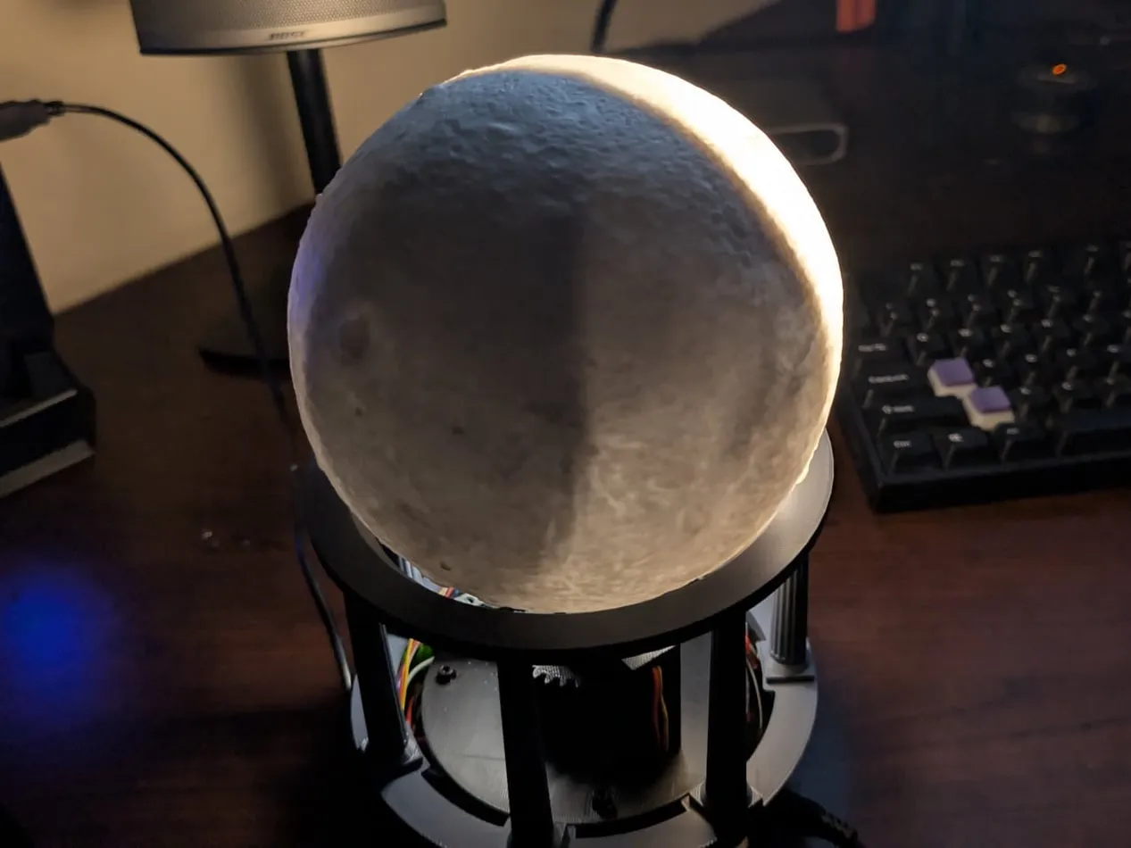
A moon lamp that shows the real phase, with a real shadow.
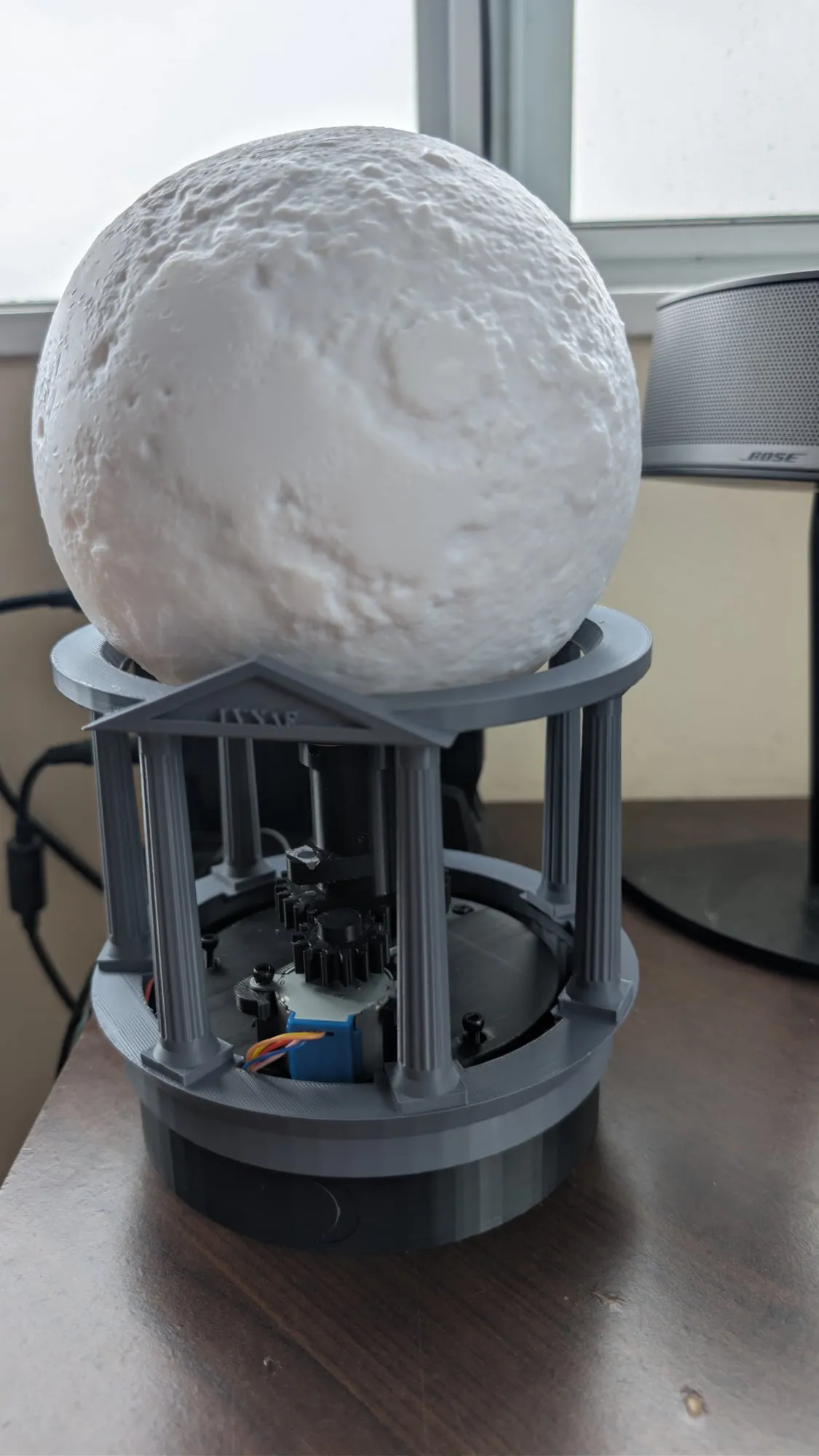
There’s no shortage of lamps that look like the Moon. You can print one yourself or buy one that’s full-featured, colourful or even levitating, in every possible size and on a plethora of bases. They look like the Moon, but they don’t behave like it.
I liked the look, so I bought one as a night light for my kids. It was battery powered, which meant I couldn’t turn it on and off with the light switch: once unplugged, it just stayed on. I figured that taking the battery out would turn it into a plug-in lamp, but these lamps are cheap and not meant to be serviced, so there was no easy way to do it without breaking it.
The lamp was pretty and the kids liked playing with it, but I could see where it was heading. Left as it was, it would soon become a soccer ball, and then trash. That was all the justification I needed to break it myself and maybe turn its fate around, so I cut out the bottom.
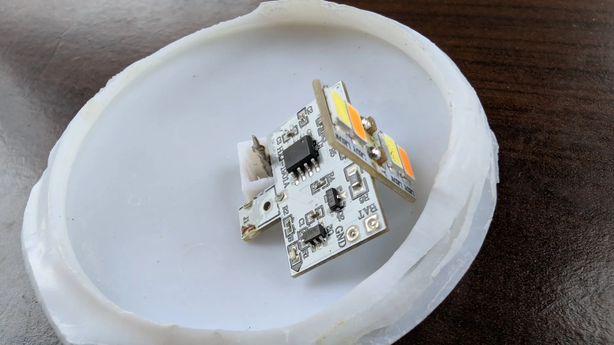
Of course, it wasn’t that simple. When the lamp gets power, its software starts off, so plugging it in doesn’t turn it on; you still have to tap the touch button. Worse, the electronics are heavily cost-optimized, so there was nothing I could easily modify. I could have bypassed the controller and switched the LEDs directly, but that might not be safe for the smarter LEDs that usually need a controller, and I’d lose all control over brightness and colour.
So I’d have to replace both the LEDs and the controller with something I could program to just turn on. That was getting complicated for a simple lamp. It also gave me an idea: if I was adding my own LEDs and my own software anyway, why not make it do more? Why not make it actually track the phases of the Moon, and its eclipses?
That’s fun for me, but a night light that goes dark at every new moon is kind of silly. Or is it? Maybe it would spark their curiosity. So it was decided: I would build one that shows tonight’s phase, a sphere lit from one side with the day/night line falling where it falls.
This is the long version: how it works, how I built it, and some of what went wrong along the way.
- The lamp design
- Why the first prototype failed
- How the optics work
- The mechanism
- The shade
- The shell, the temple and the front face
- The electronics
- The clock, and why it runs UTC
- Firmware
- What it’s made of
- Assembly order
- Calibration
- What went wrong, in order of expense
- Where it could go
The lamp design
The lamp is a gutted commercial moon shell sitting on a small temple with seven columns. At its centre is an LED head that never moves, and around it turns a shade. The edge of the shade is a loop of spring steel that draws the terminator, the line between day and night, on the shell, and car sunshade fabric behind the loop blocks the rest of the light. Turn the shade once a lunar month and its shadow follows the real Moon.
A stepper motor turns the shade one half step every 291 seconds, and a clock with its own battery keeps time through power cuts. Once a month a Hall sensor checks where the shade is, so any missed steps get corrected. A touch pad behind the crescent moon decal turns the light on and off, and during the total lunar eclipses of 2028 and 2029 the lamp should turn red.
Why the first prototype failed
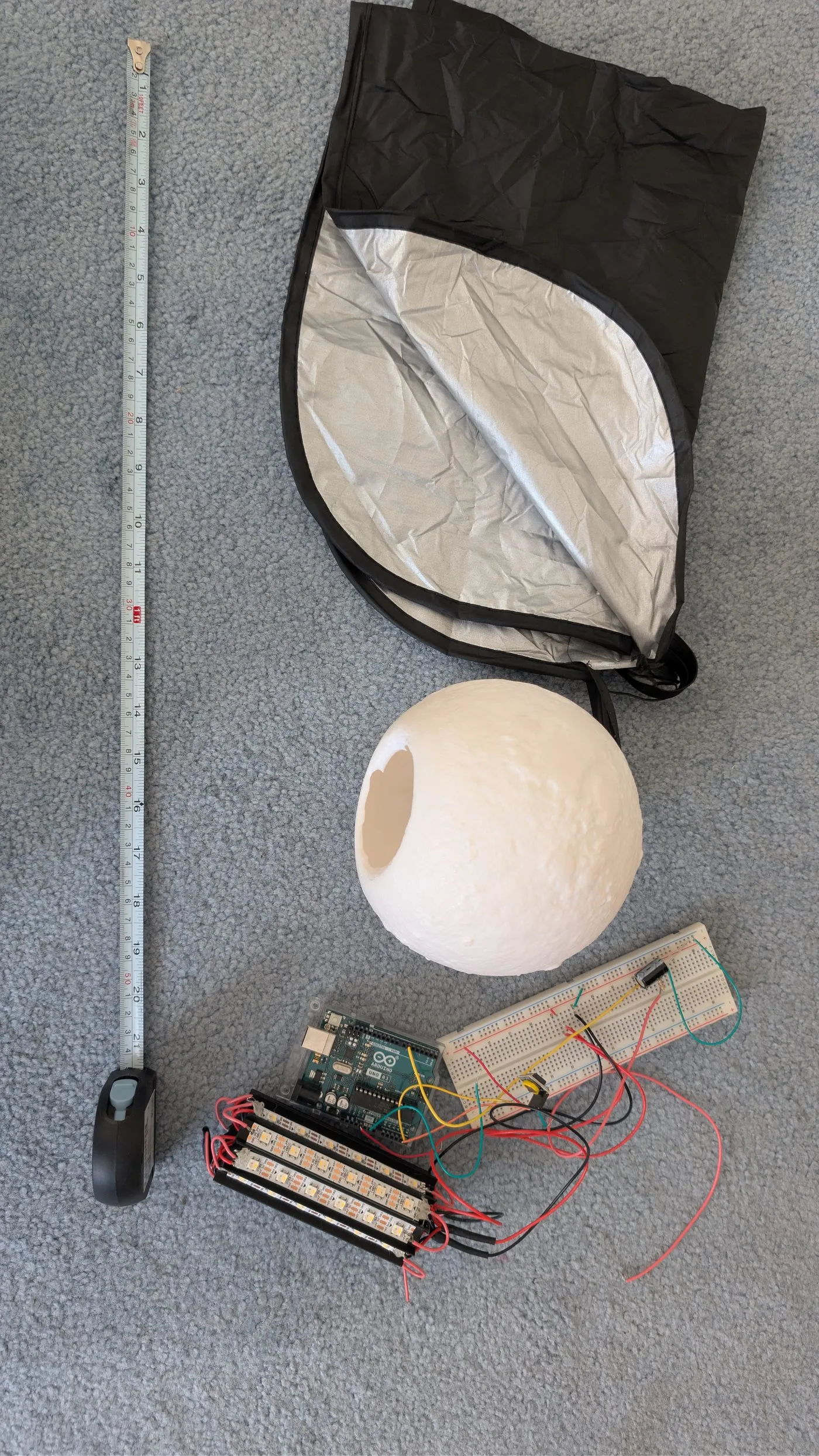
I built the first prototype shortly after coming up with the idea: a core of programmable LEDs inside the shell. The plan was to light different ribs of the core to make the phases. Even as I built it I knew it wouldn’t work, but it shifted a hardware challenge into my realm of expertise: software.
It didn’t work for two reasons.
The first is size. A shadow’s edge is only as sharp as the light source is small, and the blur (the penumbra) on the shell is
penumbra = d × (R − ρ) / ρwhere d is the light source’s diameter, ρ the shade’s radius and R the shell’s. A 50 mm light source inside a 75 mm sphere gives 12.5 mm of blur. That’s nearly 10° of longitude, or about 19 hours of lunar time smeared across the terminator, and no shade can fix it.
The second is bounce. The inside of the shell is pale, so light that lands on the lit half bounces back into the sphere, and some of it reaches the dark half. Even a single tiny light at the centre can’t make a crisp shadow on its own: the night side fills with a dim glow, and the line between day and night loses its contrast.
This nearly ended the project. The parts lay in a closet for two years, until a new technology, and some newly found free time to play with it, came to the rescue.
The failure was optical, not mechanical, so the fix had to solve both problems. For size, I threw the core away and built the smallest light I could: six pixels on a 25 mm hexagon at the exact centre of the sphere. That gives about 6 mm of blur, which reads as crisp on a sphere this size. For bounce, the shade does the work. It’s silver on the inside, to send light back toward the lit half, and black on the outside, to soak up light coming off the shell instead of letting it reach the dark half.
Making that shade turn took far more complex 3D modelling than I could manage, but by then AI-assisted development had arrived. I designed the new parts with Claude and OpenSCAD.
How the optics work
The terminator on the real Moon is a great circle: the boundary between the lit and unlit halves of a sphere. If the shade’s edge lies in a plane that contains the polar axis, and the light is at the centre, then the shadow it casts on the shell is that plane’s intersection with the sphere — also a great circle — whatever shape the edge takes within the plane. Only planarity matters. Rotate that plane about the axis and you sweep through every phase.
Two consequences that shaped the build:
- The shade only has to be opaque and out of the way. A single springy loop defines the terminator; the fabric behind it just has to block light. It does not have to be a neat hemisphere. (I learned this the hard way — see the shade.)
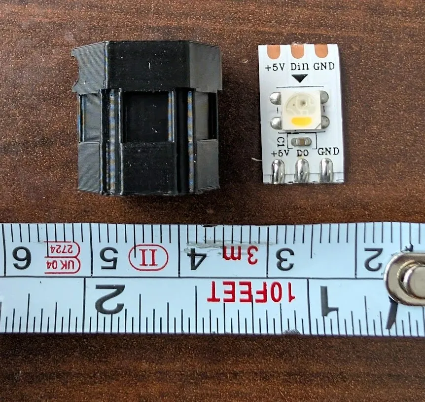
- The light must not move. Rotating the LEDs would mean a slip ring or a monthly twist-and-rewind. Instead the six pixels are fixed and the aim is synthesised in software: each facet is driven with
max(0, cos(facet_angle − sun_angle))^3, normalised so the total light is constant as the “sun” passes between facets. At most three facets are ever lit, usually two.
The shade covers 185° of longitude rather than 180° — 2.5° of over-wrap on each edge — so that new moon is genuinely dark. The cost is a 2.5° sliver at full, invisible because the sphere is fully foreshortened there. A leaky new moon would be glaring; a not-quite-full full moon is not.
The mechanism
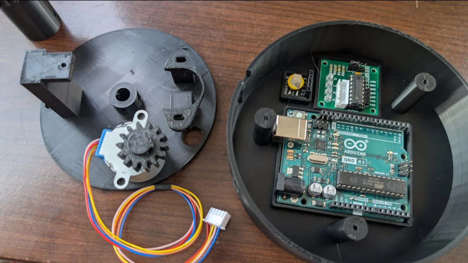
The architecture is a fixed central post with the shade rotating around it. The post carries the LED head at its top; a sleeve runs on two 608ZZ bearings around the post, 39 mm apart, and carries the platform that the shade is socketed into. The motor sits off-axis and drives the sleeve through a 30-tooth/14-tooth gear pair (module 1.5 — module 1 teeth are too thin to print reliably). The gear pair is a transmission, not a reduction; it exists only because the post is in the way.
| Half-steps per platform revolution | 8,777 (64:1 gearbox × 4,096 × 30/14) |
| One revolution | 29.53 days — the mean synodic month, 2,551,443 s |
| Step interval | 291 s |
| Step size | 0.041°, or 0.054 mm on the shell |
Between steps the coils are de-energised. Detent torque holds a shade that weighs grams and has no gravity torque about a vertical axis, and it is the difference between 0.35 W idle and slowly cooking a plastic gearbox.
The gearbox is 64:1, and I had to measure it. The 28BYJ-48 is sold in two variants — 64:1 and 63.684:1 — with nothing external to tell them apart. A small test sketch counts steps between successive Hall edges; across fourteen revolutions it read 8,778.5, which is the 64:1 figure to 0.02%. If you build one, run that test. Carrying the wrong ratio runs the shade 0.5% fast.
Homing. A magnet in the sleeve passes a Hall switch once a revolution. The firmware does not drive to home — it simply resets its step counter on the switch’s leading edge, which absorbs any accumulated error once a month. At boot it slews to the magnet at full speed (about 12 s for a revolution), then slews to wherever the clock says the shade should be. So a power cut costs nothing and nothing has to be stored.
The shade
This is the part that makes the lamp, and it is made from a car sunshade.
The loop. The sunshade’s perimeter is flat spring steel, 2.5 × 1.0 mm. Orientation matters: with the wide face tangent to the sphere it bends easily along the meridian (which is how you form it) but is 6.25× stiffer out of the terminator plane (which is the accuracy that matters). Flat stock in a matching slot also cannot rotate. Cut about 380 mm, form 17.8 mm feet straight, then the arc — the feet enter straight sockets bored into the platform at 65.4° from vertical, and a uniformly curved loop will not go in.
You do not assemble the loop outside the shell and then somehow get a 120 mm object through a 55 mm hole. Feed the strip in straight and let the shell form it: push one end in through the hole, the shell’s inside bends it round, then lock both feet into the sockets. The sockets’ entry angle does the final bend that lifts the loop off the shell wall. It does not end up as the ρ=60 mm arc on the drawing, and that does not matter — see how the optics work, only planarity counts. What to check is clearance: nothing may rub, because rubbing means stiction, and stiction means the shade binds and then jumps.
The length is cut to fit, not calculated. The loop does not bend into a true circle, so the 380 mm on the drawing is a starting point and nothing more. Start long, on purpose. Calibration has the story of trimming it.
The hole. The one I cut by hand in the shell was anything but a circle. The tungsten putty from calibration covers for that too: it fills the ragged gap between the hole and the platform, which cuts the light bleed from the bottom, the worst spot on the lamp. A future build would measure the hole against the platform and cut it properly — straight, or round, but to a line — before anything else, because everything at the bottom of the lamp seals against it.
The fabric. Sunshade fabric, silver side inward, black side facing the shell: silver reflects light back toward the lit side; black absorbs light arriving off the shell instead of kicking it across to the dark half. Three gores, generated by a small script, cut from two layers of the fabric laid one on top of the other and sewn together as a single piece — the gore pattern is sewn straight through both. A closet test showed one layer leaks to a phone flashlight and two do not. Verify opacity before cutting; the terminator is only as good as the worst pinhole. Sew every channel inward so nothing stands proud toward the shell.
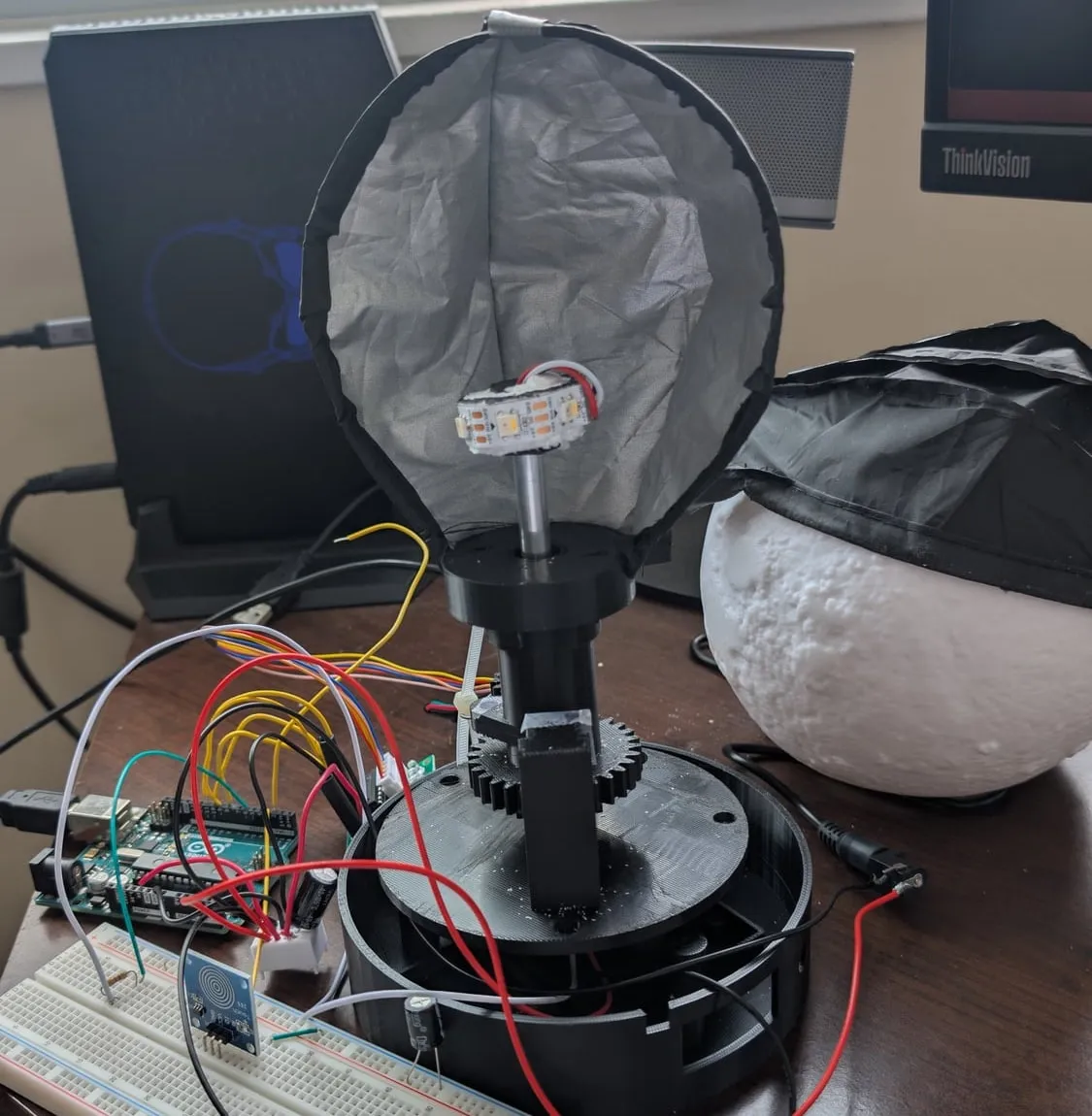
No stays. The original design had four horizontal ribs to hold the fabric in a hemisphere. They could not be assembled — a 185° arc is wider than the gap between its own ends, so fitting one inside a closed loop springs something — and worse, they pushed on the loop in exactly its compliant axis, distorting the one member whose accuracy is the whole design. Removed, the loop and fabric alone gave a clean terminator. The fabric hangs where it hangs, and at one revolution a month nothing ever disturbs it.
The shell, the temple and the front face
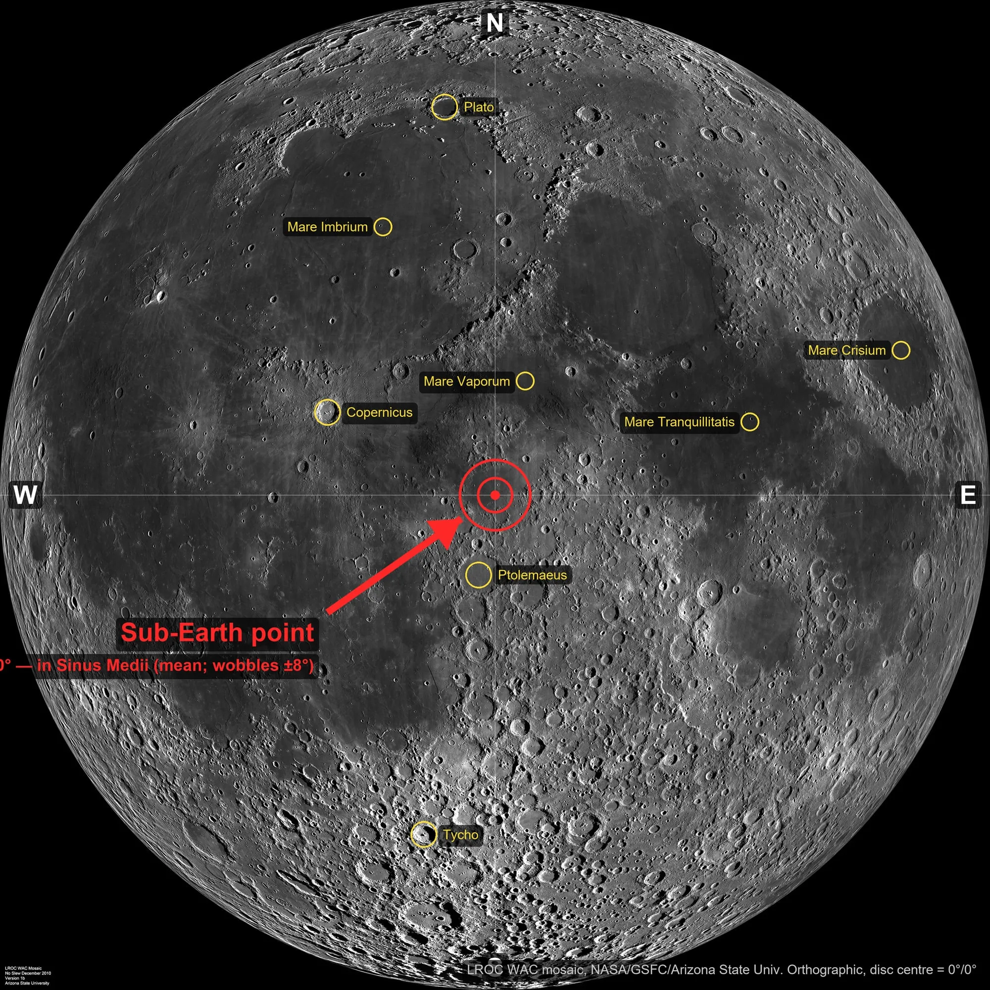
The shell carries the real lunar near-side texture, so the “front” of the lamp is not a free choice: it is whichever face shows the familiar maria, with the sub-Earth point in Sinus Medii facing the viewer. Two things follow.
The hole defines the polar axis. The rotation axis passes through the centre of the bottom hole, so a hole that is off-centre relative to the texture’s south pole tilts the whole terminator sweep relative to the seas. When recutting the hole, centring it on the pole matters far more than making it round — the stem hides roundness, it cannot hide a leaning terminator.
The Hall bracket sets the front. The magnet trips the switch at one fixed azimuth, and the firmware carries a HOME_OFFSET (measured on my build: 1,594 half-steps, 65.4°) from there to new moon. Calibrating it is geometric: freeze the clock, command a quarter phase, and the terminator should be a straight vertical line through the centre of the disc. Do not try to calibrate against lit percentage — near full it takes 154° of rotation to change the lit fraction by 1%.
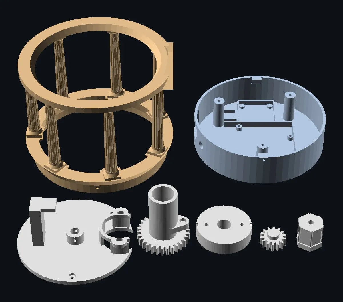
The shell rests, unclamped, on a seven-column Tuscan colonnade that slips over the tray on three grub screws. Seven for the classical planets (Luna among them); Tuscan because the Temple of Luna on the Aventine was archaic and Etruscan in style, and nothing is known of its architecture beyond that. The flutes are licence — flutes are Doric — but they hide FDM layer lines. The pediment reads LVNAE and doubles as the front-face index. The colonnade is not decorative: nothing else holds the shell, and it lifts off for service.
The electronics
| Signal | Pin |
|---|---|
| Hall switch | D2, INPUT_PULLUP |
| TTP223 touch | D3 |
| SK6812 data | D6, through 470 Ω |
| ULN2003 IN1–IN4 | D8–D11 |
| DS3231 | A4/A5, VCC from the Uno’s 3V3 pin |
Three things that are not obvious and cost me time:
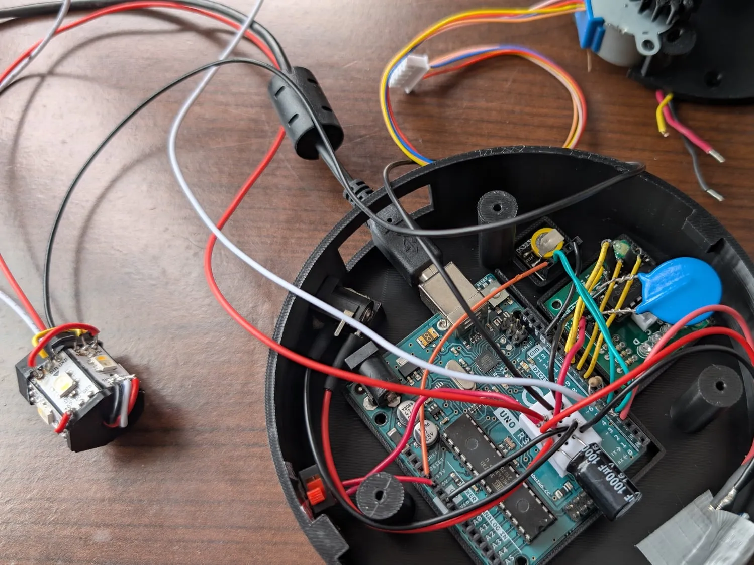
Feed the RTC from 3.3 V, not 5 V. The Pi-style DS3231 module carries a rechargeable cell and trickle-charges it from VCC. At 5 V the charger delivers ~4.3 V, over any lithium coin cell’s 4.2 V limit. At 3.3 V it undercharges slightly, which the DS3231’s 2.3 V floor tolerates. Do not lift the charging resistor — that is the fix for a module with a non-rechargeable cell, and it is the wrong fix here. Then clear the AVR’s internal I²C pull-ups after rtc.begin(), so the Uno does not drag the bus toward 5 V.
Power is a star from a screw-terminal hub, never through the Uno. The Uno’s barrel jack needs 7–12 V and browns out at 5 V; its USB path has a 500 mA polyfuse that peak draw would trip. Feed the Uno’s 5 V pin, the LEDs and the driver board each from the hub with separate returns — the stepper’s switched inductive current and the pixels’ timing-critical data line must not share a ground path. The Hall and touch sensors take 5 V from the hub but ground to the Arduino, because D2 and D3 read their thresholds against the Arduino’s ground.
The bypass caps must be ceramic. My capacitor kit is electrolytic across its whole 0.1–1000 µF range, and an electrolytic 100 nF has far too much series inductance to do a bypass cap’s job. It would be present and doing nothing, which is worse than absent because it looks handled.
A switch on the Uno’s 5 V wire. This was a last-minute addition, the small red switch in the photo below. It sits in the wire from the hub to the Uno’s 5 V pin. Open it and the Uno runs on USB alone while the supply still feeds the LEDs, the driver and the sensors. That is how I bench tested and reflashed with everything else at full power, and none of that current went near the Uno’s USB fuse. The grounds stay connected either way.
The clock, and why it runs UTC
The DS3231 keeps time through power cuts. It is set to UTC and daylight saving is never applied — the Moon’s phase is a physical event with no timezone, the lamp has no clock face, and DST rules are legislation that changes. now().unixtime() is then a true Unix timestamp and the phase is:
phase = (now − NEW_MOON_EPOCH) mod 2,551,443 sThe epoch is a mean new moon, not an observed one. This looks like a bug and is not. The lamp steps along a mean synodic month; real new moons wobble ±6–7 hours either side of that line. Anchoring on an observed new moon freezes that particular lunation’s wobble into every future prediction as a constant bias. Fitted against 125 true new moons from 2026 to 2036, the mean new moon of 2021-11-04 20:32 UTC gives a bias of 0.02°; the observed one (21:14 UTC, which every ephemeris will report) gives 0.37°; the commonly cited January 2000 anchor gives 2.0°. The remaining ±7.2° is the mean-month approximation itself, and no epoch removes it. That is ±0.6 day, and acceptable for a lamp.
(The Moon on the home page uses the same formula and the same epoch.)
Setting the clock: with the serial monitor open at 57600 baud, type T<unix seconds>. The firmware reports a flat battery rather than guessing a time, so a lamp with a dead cell parks dark at new moon instead of looking plausibly wrong.
Firmware
The firmware is one Arduino sketch, on purpose: about 1,600 lines, half of them comments explaining why. Libraries: RTClib and Adafruit_NeoPixel from the Library Manager; the half-step sequence is fifteen lines and avoids a GPL stepper library. Build: Arduino Uno, 57600 baud serial.
The loop is seven non-blocking calls: advance the clock, debounce the Hall, debounce the touch pad, step the shade toward where the clock says it should be, recompute the six pixel weights if it moved, run the fade. The shade and the boot slew share one code path; they differ only in how far behind the shade is.
Controls. One touch pad, behind the moon glyph on the tray:
| Lamp state | Gesture | Result |
|---|---|---|
| off | tap | on, at default brightness with a 1 s fade |
| off | hold 3 s | demo — one full revolution in 12 s, then back to tracking |
| on | tap | off |
| on | hold ≥ 0.5 s | brighten while held |
The lights-off state is software only; the clock, stepper and tracking keep running, so switching back on shows the correct phase with no catch-up.
Eclipses. During the umbral phase of the total lunar eclipses of 2028-12-31, 2029-06-26 and 2029-12-20 the lamp fades to red, holds through totality, and fades back — over about three and a half hours, as the sky does.
A compressed time base is what makes it testable. At 1× the shade moves a half-step every 291 s and passes the magnet once a month; nothing can be observed on that cadence. The serial keys 1, 2, 3 run the clock at 3600×, 86400× (a month in 29 s — the useful one) and 207000× (the mechanical ceiling); P<0–99> jumps to a percentage of the month; f freezes; e rehearses an eclipse at 600×; s prints everything the lamp knows. The rate never persists across a boot, so a lamp cannot silently come up fast.
--- status ---
clock   1789598184 UTC
age     5.25 of 29.53 d
shade   at 1594 want 1560 ahead 8743 of 8777
emitter phi_s 116 deg
eclipse none
hall    DETECT, armed
state   tracking
rate: 1x (live -- the clock is the RTC)
What it’s made of
Everything here is a stock part. The 3D-printed pieces were quoted and printed by a local shop because I do not own a printer.
Electronics
| Part | Notes |
|---|---|
| Arduino Uno R3 | any 328P board works but the tray is sized for an Uno |
| DS3231 RTC module | the Raspberry Pi 5-pin type with a rechargeable cell — runs at 3.3 V, see the electronics |
| 28BYJ-48 stepper + ULN2003 driver, 5 V | the ubiquitous one |
| 6× SK6812 RGBW pixels | cut from a strip |
| A3144 Hall-effect switch + 6×3 mm neodymium disc | homing sensor |
| TTP223 capacitive touch module | senses through the tray wall |
| 5 V, 2 A supply, barrel jack, screw-terminal hub | never through the Uno’s own jack |
| Small switch | in the 5 V wire from the hub to the Uno, to cut the Uno off from the supply during bench testing |
| 470 Ω resistor; 470–1000 µF electrolytic; 2× 100 nF ceramic | the ceramics matter |
Mechanical
| Part | Notes |
|---|---|
| 150 mm “moon lamp” shell | the printed-texture kind; gutted, hole recut on the texture’s south pole |
| 2× 608ZZ bearings | skateboard bearings; these carry the whole rotating stack |
| 8 mm OD × 6 mm ID aluminium tube, 142 mm | the fixed post; LED wires run up the inside |
| M3 × 8 grub screws, cup point (~15) | every non-bonded joint is one of these |
| Two-part epoxy | bearings into the sleeve |
| A car windscreen sunshade | supplies both the flat spring-steel perimeter strip and the black/silver fabric |
| Tungsten Putty | around the perimeter of the shell hole to invisibly weigh it down |
Printed parts
Seven parts: base plate, with the post boss, motor yoke and Hall bracket printed as part of it · sleeve with integral 30T gear and magnet lug · 14T pinion · platform · hexagonal emitter head · electronics tray · the temple.
Assembly order
This was genuinely the hardest part of the build — not the design, the assembly. The clearances are tiny, the tray is crowded, and I spent hours soldering wires I should have crimped. What went wrong has the specifics and what I would change; the order below is what has to happen regardless.
The order is constrained, because the tray screws and motor screws are unreachable once the shell is on:
- Find which face of the magnet trips the A3144 and mark it, before the magnet goes into the sleeve’s lug. The sensor only answers to one pole.
- Hall sensor into its bracket pocket before the sleeve — it loads from the arm’s underside.
- Base plate onto the tray’s three pillars, screwed from above.
- Motor into its yoke, then the sleeve, then the pinion — the sleeve’s gear cannot pass an installed pinion.
- Bearings load into the sleeve from below, epoxied. Post through them, grub-locked in the boss, with a 1 mm shim under the lower race.
- Platform onto the sleeve; head last, since it is wider than the platform’s bore.
- Set the gear mesh on the yoke’s slotted holes; check it turns freely by hand.
- Run the motor and Hall test sketch to verify stepping, homing and the step count.
- Last come the shade and the shell, which go on together. That job has a section of its own.
Calibration
I would love to say that I assembled it once and everything worked. It did not.
The loop and the shell
The first problem was the terminator loop. It was too long, and it does not bend into a perfect circle, so the shell rested directly on the loop, almost a full centimetre above the temple’s cradle. Turning the shade then turned the shell with it.
So I cut a tiny piece off the loop, put everything back together and checked two things: how high the shell sat above the cradle, and how much of the loop touched the shell. Then I did it again. Where the loop touches the shell the terminator looks its best, because the loop blocks the bleed completely, but at first it only touched at the top. Every cut lowered the shell closer to the cradle. It also made the loop harder to fit, and one cut too many would pull the loop off the top of the shell and let light bleed over it.
After a couple of cuts I stopped and pressed tungsten putty around the opening in the shell instead. A little weight pushes the shell down on the loop and bends it into a better circle, so the sides of the loop sit closer to the shell and not just the top. It also gives the shell some friction against turning with the shade.
The software
The software calibration was much easier.
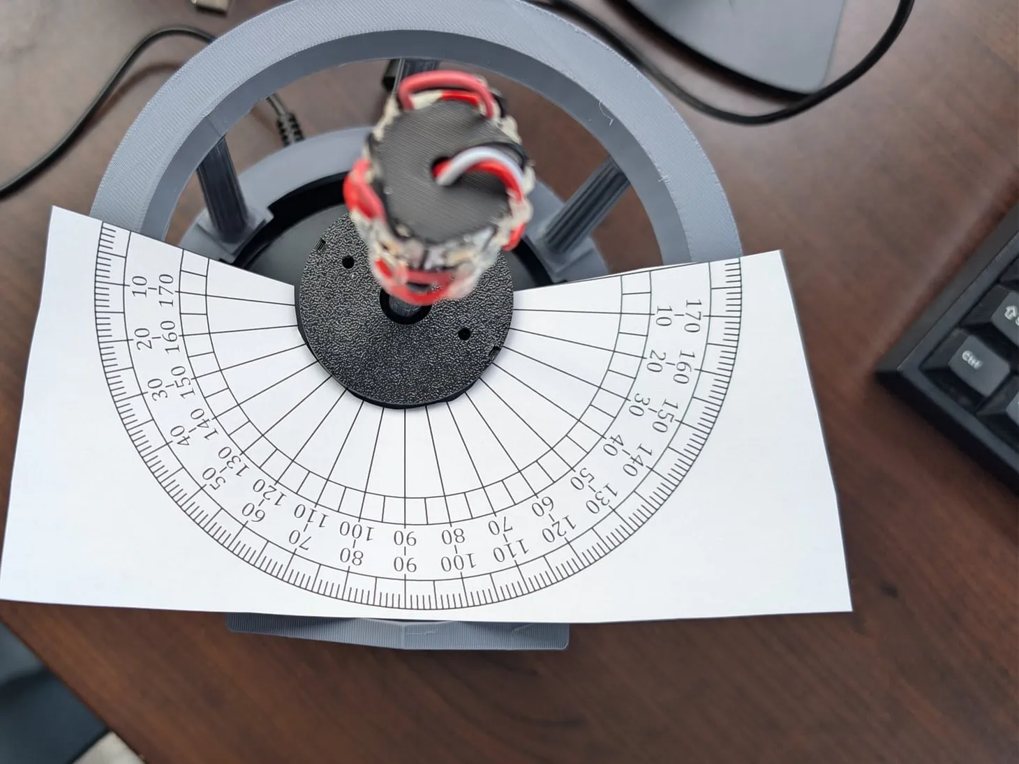
- Count the steps. A test sketch counts half steps between passes of the magnet. Mine read 8,778.5 over fourteen turns, which settled which gearbox I had.
- Set the front. With the clock frozen, command a quarter phase. The terminator should be a straight vertical line through the centre of the disc, and
HOME_OFFSETis whatever makes it so. On my lamp that is 1,594 half steps, or 65.4°. The front face has the reasoning. - Set the clock. Type
T<unix seconds>in the serial monitor, in UTC. - Run a month in half a minute. Press
2for a day per second, withsprinting the status. Watch it home, catch up and pass the magnet. The correction it prints at the magnet should be under 2°.
Then put the shell on and wait for dark.
What went wrong, in order of expense
The first print batch bought a defect list. Six parts, CA$113, none of which went into the lamp: 23 defects, 12 of them blockers — the motor shelf was smaller than the motor, the motor opening was round and the motor is not, the tray pillar blocked the Uno’s USB port, the Hall pocket had nowhere for the leads to go. Not one had been caught by a render, because the clash check only compared printed parts against printed parts and never included the motor, the boards or the sensor. The redesign added the bought parts as geometry and the check immediately found three more. That is why I had to order prints twice. Model the things you buy, not just the things you print, and run the clash check before you order.
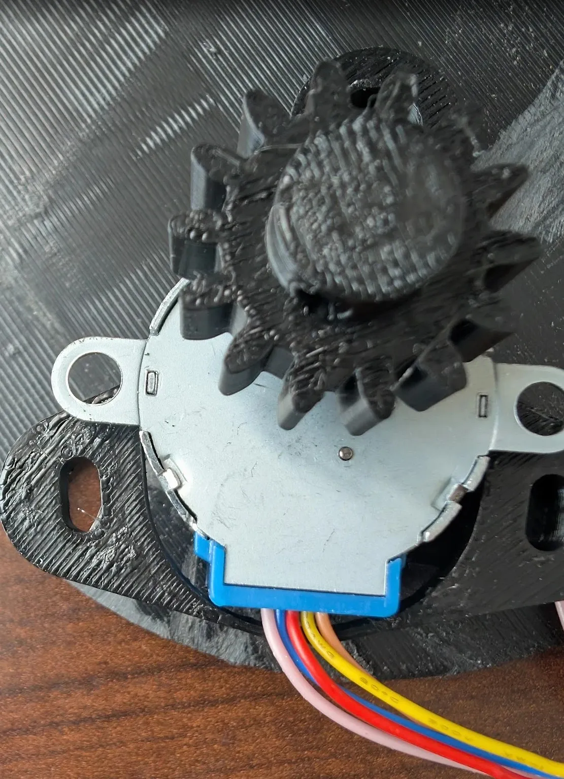
The 28BYJ-48’s shaft is not concentric with its can — 8 mm off. The yoke had to be built about the can’s axis while the pinion follows the shaft.
“Undetectable” was true for the wrong quantity. The 12 mm gap between shade and shell was sized on penumbra math, which said closing it would buy nothing. On the built lamp, with all six pixels on, light flowed sideways around the gap and lit the dark hemisphere from behind. The penumbra calculation bounds edge blur, not annulus leakage. Under a real lobe (at most three facets lit) it is acceptable; a felt lip along the loop is the fix if it ever isn’t.
When a clash check returns a number, locate it before deciding what it is. A 0.12 cm³ result I explained away as faceting was a 5 mm collision between the pediment and the shell.
Testing under compression never exercises the 1× path. Everything about the motor was verified at 86400×, where the coils are effectively never dark. The isolated cold step at 1× — energise, hold, release — only exists in service. The first version released the coils 100 µs after the step; the shade buzzed and the counter advanced regardless. Also, on the very last bench day, the lamp sat still for hours after booting: it had homed within 100 half-steps ahead of the target and was correctly waiting for the Moon to catch up. That window is 8 hours a month and, by coincidence of the calibrated home offset, it was that afternoon.
Bench test the physics before you print anything. Skipping it cost the most.
And what made the assembly hard
None of these cost money. They cost evenings.
The Hall sensor’s leads. The bracket’s pocket and lead channel are sized to the datasheet with tiny allowances, and in practice I drilled a much larger hole for the cable. The A3144’s own three legs are close together and keeping them from touching each other while pushing the sensor up into its pocket was the single most fiddly job in the build. Next time: a purpose-made enclosure for the sensor that physically separates the three leads and gives the cable somewhere to go before it heads down under the base plate.
The tray is full. The Uno, the driver board, the RTC, the hub, the decoupling caps and every cable share a 130 mm dish, and the ceramic capacitors I bought are large. It closed, but only just. A smaller tray for a Nano — which I had down as the obvious way to shrink the lamp — would have made this worse, not better. Any future version needs dedicated printed enclosures for the capacitors and the touch module before the tray gets any smaller.
M3 grub screws into printed plastic are horrible. They do not cut a proper thread in FDM walls; they displace material, hold by friction, and can be pulled straight back out. The ones in the base plate “hold” the post by that friction alone. A future design would keep M3s but orient every one so that it locks the part by blocking lateral movement — a pin through a hole that resists shear — and never so that the joint depends on the thread’s pull-out strength. Where a joint really needs a thread, a heat-set insert.
Crimp, don’t solder. Nearly every connection in the lamp is soldered and heat-shrunk, and nearly every one of them took multiple attempts in a cramped tray with a hot iron near other wires. Proper crimped pins and housings — Dupont, JST, whatever — would have saved hours and made the thing serviceable. The only soldering I would keep is the LED head, where the six segments chain with three conductors each and there is no room for a connector.
Where it could go
- A felt lip on the boundary loop, brushing the shell.
- Better packaging before a smaller footprint. A Nano would let the 130 mm tray shrink to about 100 mm, but not until the capacitors, the touch module and the Hall sensor each have an enclosure of their own and the cables have connectors instead of solder joints. Shrinking the tray first would just make the problems above worse.
- Libration and the sub-solar latitude are deliberately ignored: the sub-solar point never leaves ±1.5° of the equator, which is why a single equatorial ring of pixels is correct and rings above and below would be wrong.
If you scrolled this far
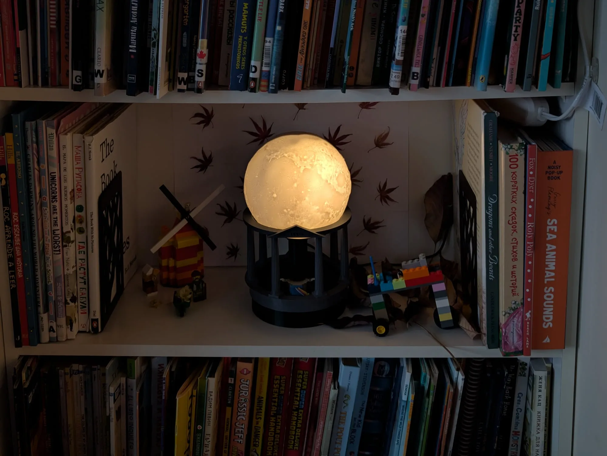
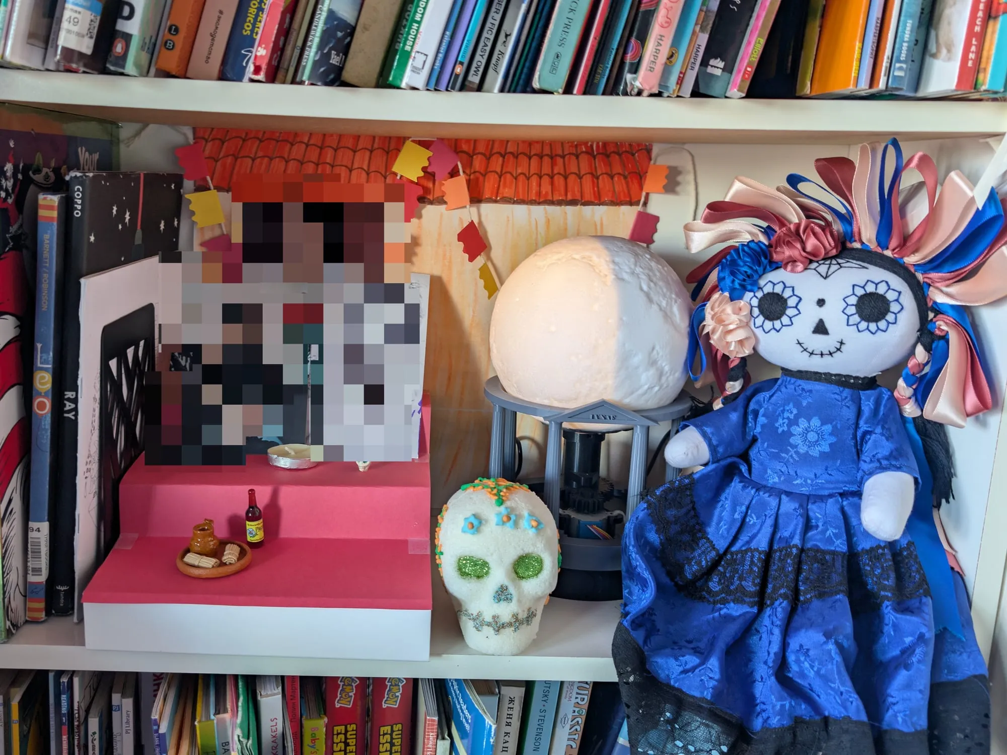
Thanks for reading. Here’s Luna at home.